Three mmWave Systems Driving RF Front-End Demand: 77 GHz Radar, 5G mmWave and LEO Satcom
Millimeter-wave frequencies — conventionally 30–300 GHz — have moved from laboratory radios into shipping products in three distinct markets: automotive radar at 76–81 GHz, 5G fixed and mobile access at 24–40 GHz, and low-Earth-orbit (LEO) satellite user links at Ku/Ka band. The systems look different from the outside, but from the RF front-end they impose a remarkably similar requirement set: electronically steered arrays, low-loss passive front-ends, and tight integration between switches, phase shifters and antennas.
This article surveys each system, its frequency bands and architecture, and the common RF building blocks they create demand for.
1. 77 GHz automotive radar

Bands. The long-range radar (ACC, highway pilot) moved from 24 GHz to the 76–77 GHz band, while 77–81 GHz covers short/medium-range radar (SRR/MRR) and imaging radar with up to 4 GHz of sweep bandwidth. The wide bandwidth directly sets range resolution: 4 GHz FMCW chirps resolve objects on the order of centimetres, enough to separate stopped vehicles from overhead signs.
Architecture. A modern 77 GHz radar is an FMCW or (increasingly) CMOS-coded-MIMO system built around an RFCMOS transceiver IC with multiple TX/RX channels, cascaded boards for imaging radar (up to 12×16 virtual elements and more), and a planar patch antenna array in package substrate or PCB. Front-end content per module includes:
- PA and LNA integrated in the RFCMOS or SiGe chip;
- transmit–receive switching and isolation structures;
- high-Q transmission lines and antenna feeds on low-loss substrate;
- stable frequency references and clock distribution;
- radar signal processing ASSP behind the front-end.
The antenna and the package are designed together — AiP (antenna-in-package) is mainstream at 77 GHz because a coaxial connector at this frequency wastes more power than the PA produces.
Reliability profile. AEC-Q100 qualification, operation to 105 °C module temperature, and robust behavior under radome contamination and mutual interference between vehicles define the component choices.
2. 5G mmWave radio units and user equipment
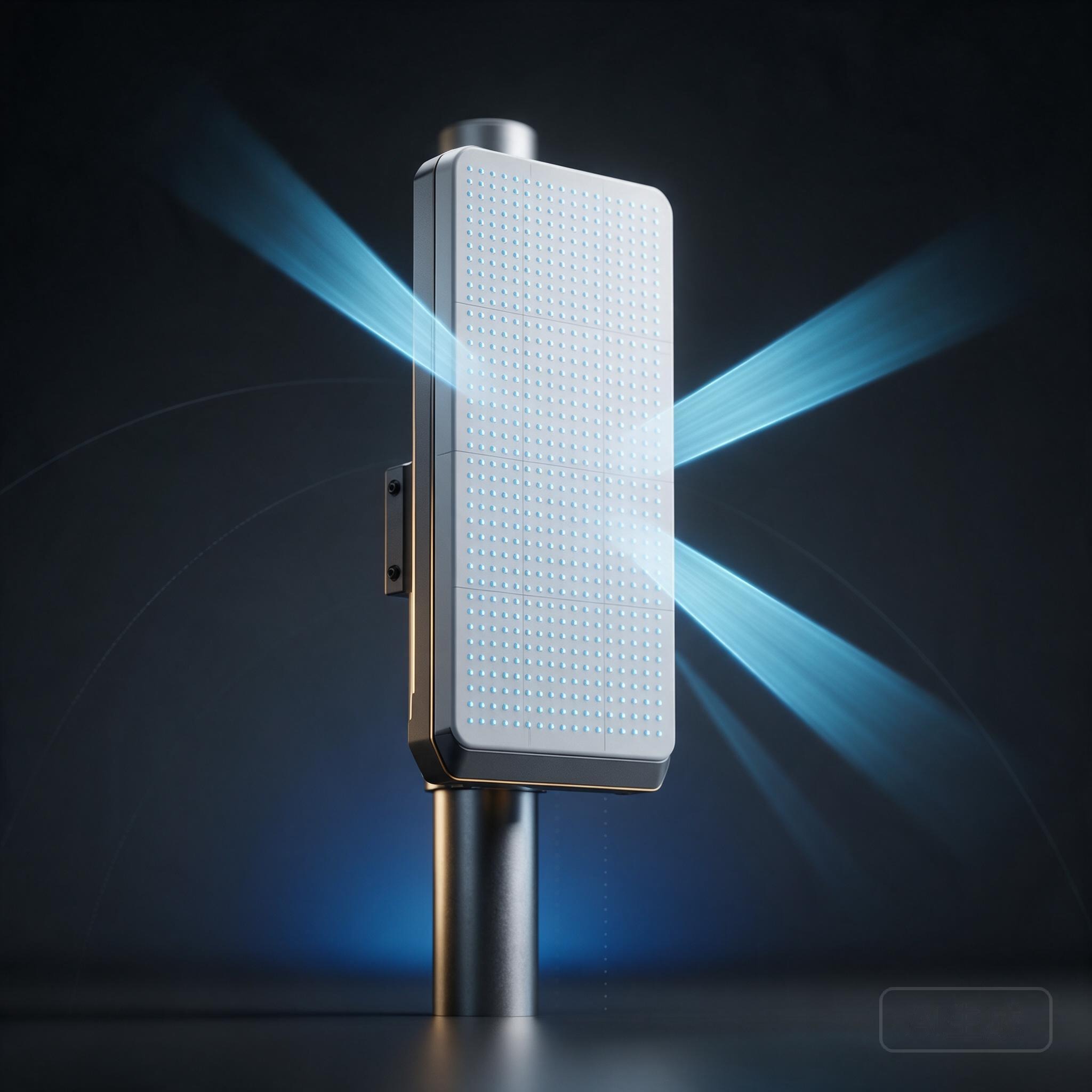
Bands. 5G FR2 deployments use n257 (26.5–29.5 GHz), n258 (24.25–27.5 GHz), n260 (37–40 GHz) and n261 (27.5–28.35 GHz), with 3GPP defining channel bandwidths up to 400 MHz. At these frequencies free-space and foliage/rain losses force the link budget into an array: only beamforming gain closes the range.
Base-station side. An mmWave AAU (active antenna unit) is effectively a phased array tiled with silicon beamformer ICs driving sub-arrays of patch antennas through a multilayer low-loss PCB or LTCC. Each beamformer channel integrates phase shifter, VGA, T/R switching, PA and LNA — the same functions as a classical T/R module, miniaturized in silicon or with GaAs PA stages. Thermal density and per-element calibration are the dominant engineering problems.
Handset/CPE side. Space is the constraint. The front-end uses AiP modules — the antenna, beamformer, up/down converter and IF line are co-packaged behind a plastic window — often two or three modules pointed in different directions because a hand grip can shadow the whole array. Capacitive and ohmic MEMS switches remain attractive for antenna selection and aperture tuning because their loss and linearity beat solid-state alternatives, even though most shipping handsets currently use SOI; MEMS content appears first in infrastructure and CPE where the loss savings justify packaging complexity.
3. LEO satellite communication terminals

Bands. LEO constellations use Ku band downlink (around 10.7–12.7 GHz) and uplink (14–14.5 GHz), and Ka band (roughly 17.8–21.2 GHz downlink, 27.5–31 GHz uplink), with new constellations proposing direct-to-handset links at L/S band. Unlike GEO satellites, LEO satellites move across the sky at hundreds of kilometres altitude, so a fixed dish cannot track them.
Architecture. The winning form factor is the flat-panel electronically steered array — a low-profile radome over hundreds to thousands of patch elements grouped into sub-arrays, each fed by a beamformer IC with independent phase and gain. The terminal must maintain one (or several) beams toward moving satellites and hop between satellites as they pass below the horizon, which requires sub-microsecond beam switching and constant calibration against temperature and element failure.
Front-end content per terminal is large: dual-polarized elements, PA/LNA beamformer chains, switched-line phase shifters, T/R switches, up/down conversion blocks, and a high-precision GNSS/inertial antenna-pointing solution. Passives on low-loss glass or ceramic carriers and thin-film IPD technology are increasingly used to keep per-element feed loss inside the link budget across thousands of elements.
What the three systems share
| Requirement | Consequence for the front-end |
|---|---|
| Electronic beam steering | Phase shifter + VGA + T/R switch per element |
| High path loss at mmWave | High-EIRP arrays, low-loss feed networks, AiP |
| Thousands of elements in an array | Yield, calibration and per-element power become system-level |
| Tight thermal envelope | GaN/GaAs/silicon PA mix chosen by power and efficiency |
| T/R duplexing in one aperture | High-isolation switches or circulators |
| Frequency above 10 GHz | Low-loss substrates: glass IPD, fused silica, alumina, HR silicon |
| Fast beam hopping | Switching speed and control bus bandwidth |
Implications for component sourcing
Across all three systems the same engineering questions appear: what is the per-element insertion loss through switch and phase shifter, what power can the PA deliver at acceptable efficiency, how is the antenna packaged with the electronics, and how stable are passive values over temperature? Answering them pushes designs toward low-loss thin-film passives and filters, switched-MEMS or high-linearity solid-state switches, and antenna-in-package integration on low-permittivity carriers.
Whether the end product is a bumper-mounted radar, a street-level mmWave small cell or a rooftop satcom dish, the front-end architecture converges: a calibrated, electronically steered array built from tightly integrated T/R channels — which is why component demand across the three markets moves together even though the end customers do not.